How to Choose an OTDR for FTTH and Access Networks
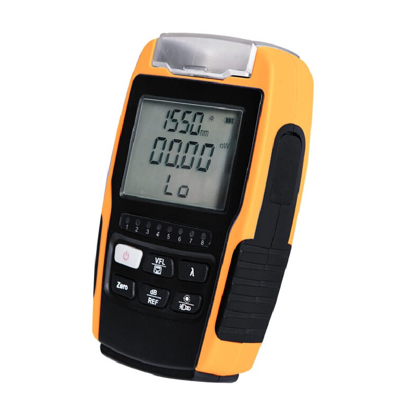
An OTDR is the instrument crews reach for when a fiber link needs to be characterised, not just checked: where is the break, how long is the span, which splice or connector is losing light, and did the installed link come out as designed? For FTTH and access networks the buying mistake is usually buying by a single headline number. The right OTDR depends on the length of your spans, how closely spaced the events on them are, whether you test through splitters, and whether the crew also needs the OTDR to cover everyday power-meter and fault-locator jobs.
This guide explains the concepts that decide the choice — dynamic range, wavelength, dead zones, and launch fiber — in plain terms, then maps them to FTTH and access work. Browse fiber test equipment as you read.
What an OTDR trace actually shows
An OTDR sends pulses of light into the fiber and measures the light that comes back over time. The result is a trace: distance along the horizontal axis, loss along the vertical axis. Connectors and mechanical joints appear as reflective events — a spike with a step down. Fusion splices appear as a small step, usually without a spike. A break or the fiber end appears as a spike followed by the trace dropping to noise. Bends show as loss steps that differ between wavelengths.
Everything else in this guide follows from that picture: the instrument has to launch enough light to see to the far end of your longest span (dynamic range), resolve events that sit close together (dead zones), and do it at wavelengths that reveal the faults you care about.
Dynamic range: enough for your longest span, with margin
Dynamic range, expressed in dB, describes how much loss the OTDR can see through — in practical terms, how long and lossy a fiber it can characterise with a usable trace. A span's total loss includes fiber attenuation over its length, plus every splice, connector, and splitter in between.
For FTTH, the splitter dominates the budget. A link through a high-ratio splitter loses far more light at that one point than the short fiber sections either side of it. An OTDR intended for testing through splitters therefore needs substantially more dynamic range than one used only on short, splitter-free links — even though the distances are short. For access and metro spans without splitters, distance and accumulated splice loss set the requirement instead.
The practical rule: add up the worst-case loss of the longest, lossiest link you must certify, and choose an instrument whose range covers it with margin to spare, using the pulse and averaging conditions you will actually use in the field. A range figure quoted under very long averaging and the widest pulse is not the range you will experience on a quick fault-finding job.
As one in-range example, the K-100 multi-function OTDR operates at 1310/1550 nm and combines OTDR, optical light source, optical power meter, VFL, and RJ45 sequence and length testing in one unit, with results stored in SOR and PDF formats — a format aimed at crews who want testing and basic verification in a single instrument. Larger standalone OTDR work is covered by models such as the K-600 OTDR — compare models on the selection criteria in this guide and ask for the full specification for your span types before deciding.
Wavelengths: why 1310 and 1550 nm are the standard pair
Single-mode access fiber is routinely tested at 1310 nm and 1550 nm. Testing at both wavelengths is not duplication:
- Bend sensitivity differs. A bend or tight radius that shows modest loss at 1310 nm typically shows more loss at 1550 nm. Comparing the two traces helps separate a bend from a splice problem at the same distance.
- Faults characterise differently. A loss step that appears at both wavelengths in similar size points to a splice or connector; one that grows sharply at 1550 nm points to bending.
- Records need both. Installation records for access fiber are normally kept for both wavelengths so later maintenance traces can be compared like for like.
For FTTH maintenance on live networks, testing strategy also has to consider in-service monitoring wavelengths and filtering — if your crews will ever test lit fiber, raise that requirement explicitly when you buy, because it changes the instrument specification.
Dead zones: the deciding factor on short, dense links
After a reflective event such as a connector, the OTDR needs a short distance to recover before it can accurately measure the next event. That blind stretch is the dead zone. Two related figures matter: the event dead zone (how close two reflective events can be and still be seen separately) and the attenuation dead zone (how far after an event before loss can be measured accurately).
On long backbone spans with events kilometres apart, dead zones are rarely the problem. On FTTH and access links — a connector at the cabinet, a short patch, a splice a few metres later — events crowd together, and a long dead zone can hide the very fault you were sent to find. Shorter dead zones generally come with shorter pulse widths, which in turn reduce the range the trace can cover. That trade-off is why pulse selection and automatic test modes matter in the field: the crew needs a setting that resolves the cabinet area and still reaches the far end.
Launch fiber: the cheap accessory that fixes the first connector
An OTDR cannot properly measure the connector at its own front panel — that connector sits inside the instrument's initial dead zone. A launch fiber (a known length of fiber between the OTDR and the link under test) moves the link's first connector out into measurable trace, so its loss and reflectance can be read. A receive fiber at the far end does the same for the last connector.
For crews certifying FTTH drops and short access links, a launch fiber is not optional kit; without it, the two end connectors — the most handled and most failure-prone points — are the two points you cannot document. Budget for launch and receive fibers with the same connector types your network uses, keep them clean and protected, and treat them as part of the OTDR purchase.
OTDR, or power meter first?
An OTDR locates and characterises; a power meter and light source measure total loss directly. Most FTTH verification can be done, and is often formally done, with a power meter: the K-527 optical power meter is a handheld meter for optical power and link loss measurement, and the K-PV1 power meter + VFL combines a power meter measuring −70 to +10 dBm with a 10 mW visual fault locator in one 2-in-1 unit. A VFL such as the K-V10 visual fault locator (10 mW, 650 nm) finds breaks, tight bends, and the wrong patch lead by visible red light over short distances.
A sensible fleet pattern is: power meter and VFL in every install kit, OTDR with the commissioning and repair crews who locate faults and document spans. If budget forces one purchase first, buy the instrument that matches the questions you are actually asked: "what is the loss?" needs a power meter; "where is the fault, and which splice is bad?" needs an OTDR.
Selection checklist
- [ ] Longest and lossiest span listed, including splitter loss where fitted
- [ ] Dynamic range covers that span with margin under field test settings
- [ ] 1310/1550 nm testing confirmed for single-mode access work
- [ ] Event and attenuation dead zones short enough for your cabinet and drop spacing
- [ ] Launch and receive fibers included in the plan, with matching connectors
- [ ] Trace storage and reporting format (for example SOR and PDF) fits your records
- [ ] Power meter and VFL coverage decided — separate units or combined
- [ ] Connector types and cleaning kit planned — an OTDR trace on a dirty connector is wasted work; see wet-to-dry fiber end-face cleaning
The short version
Choose an OTDR by span, not by headline: enough dynamic range for your lossiest link, 1310/1550 nm testing, dead zones short enough for dense FTTH events, and a launch fiber in the case. Pair it with a power meter for direct loss measurement, and you can both find faults and prove the fix.
Describe your spans — lengths, splitter use, and connector types — via the contact form on this site or on WhatsApp at +86 150 6823 2998, and we will help you narrow the fiber test equipment options, including the K-100 and the K-600, to the test setup your crews actually need.